Rails and Trails Imaging
HomeAbout UsPhyllis' GalleryKeith's GalleryBooksModel RRContact Us

Model RR - Creating Graphic Control Panels
Please check back for future additions to this page.
I have been successful at creating some graphic and attention-getting control panels that are worth the time it takes to make them.  I draw the track schematic to the actual size of the panel using any number of programs which have basic drawing tools.  My favorite is Adobe Photoshop 7.  I select colors that contrast and I measure carefully to assure that spacing is adequate to install toggle switches and indicator LED's.  When the plan is accurate and completed, I mark the centers for the holes to be drilled on a second but otherwise identical file.  I print that copy as a drilling template, sandwich it between 3/16" sheets of Plexiglas, clamp securely, and drill the holes.  I do this to avoid tearing the original while drilling the holes.  Then I separate, clean the edges of the holes with a sharp #5 blade, print the original on very thin high-quality inkjet paper, reassemble the sandwich, cut the holes through the paper with an sharp #5 blade,  mount the sandwich in the panel frame, and mount the toggle switches.  The toggles hold the sandwich tight together even in the center of the panel.  The control panel is now ready to be wired.  LED's can be used behind the panel to illuminate it.
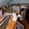
To play slide show, click on the 1st picture.
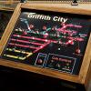
Control panel for Griffith City is installed on the front edge of the layout.
Detail of panel with indicator LED's, push button switches for turnout control, and toggle switches for track power.
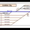
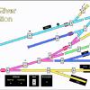
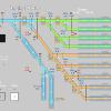
I start the design layout by drawing a schematic of the track plan and include some key structures and track references.
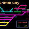
Inkjet printout of the finished track plan.  I always use a black background and contrasting colors.  This panel can be illuminated from behind by LED's.
This is a drilling template (not the same panel) showing the placement of toggles and LED's.  The toggles are the actual size; so the placement and spacing on the schematic can be accurately checked.
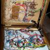
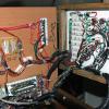
The hinges for this panel are on the bottom; so it opens face down and flat.  It is easy to complete the wiring from a chair.  Notice the backside of the toggles and panel mounted LED's.
I place all the terminal connections and resistor networks inside the bottom of the panel.  Only wires run under the layout.
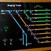
The is the finished control panel for the staging yards.  Here I have used momentary toggles to align the turnouts instead of push buttons.  There is a direction indicator at the top because this area is totally hidden, except for video.
This is the drilling plan for the same control panel.  Alignment and spacing of the toggles was critical.
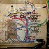
This panel is hinged on the side to swing open horizontally.  There are so many wires for the LED indicators that the panel has to be carefully closed. Also It is so thin that most wire connections are located below it instead of behind it.