Rails and Trails Imaging
HomeAbout UsPhyllis' GalleryKeith's GalleryBooksModel RRContact Us

Model RR - Designing Electrical Access
To play slide show, click on the 1st picture.
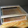
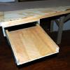
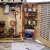
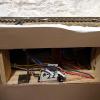
Electronics drawer showing frame as it sits ready to install.
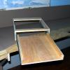
Pullout when fully extended provides easy access to terminals or circuit boards in the back.
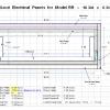
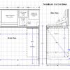
Schematic of construction plan for drawers.  It is designed for attachment under the support trusses.
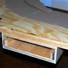
Drawer is installed under bench work.  The pullout extends for attachment to face frame and the thickness of the fascia.
Drawer when fully extended provides easy access from a sitting position.  Great concept for us aging model railroaders.
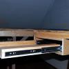
Side view showing full extension ball bearing drawer slides.
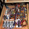
This drawer is loaded with terminals and circuit boards.  The terminals are used for switch machines, track section power, and IR train detectors.  The circuit boards in each drawer control other localized events such as crossing signals.
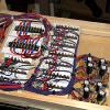
This drawer is deeper to hold 2 levels of terminals and circuits.  The CD units are seen in the front for localized switch machines.  Also note the use of labels for the terminal strips.
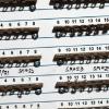
Terminal strip labels were designed for specific purposes like switch machines, track sections, and lug terminals of various lengths.  They are mounted in place using contact cement and the terminals screw mounted on top of them.
Drawers for Easy Access
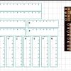
One solution for easy access of electrical terminals and circuit boards is full extension drawers.  I built 3 of these and would have used more if space had permitted.  The fronts can be control panels or track diagrams.  Included is a dimensional schematic of the drawers and the printed labels I designed for terminal lug strips.
Train Brain Control Center
Perhaps one of my best ideas for easy access and centralized control is a box that I designed which mounts under the front edge of the computer desk.  For access, it swings up and opens like a clam shell.  Inside are many connections and circuit boards.  Troubleshooting and soldering is done from a desk chair.  This concept has proven to be everything I had hoped for and then some.
To play slide show, click on the 1st picture.
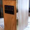
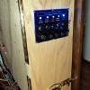
Front of Train Brain centralized control box only contains power switches, indication LED's, and fuse holders.
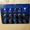
Detail of power control panel showing LED indicators, toggle switches, and fuse holders.
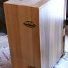
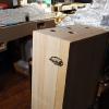
This view is the backside of the box showing the closure latches.  This side faces forward when the box is rotated in the up position.  See other views for clarity.
Undo the latches and the box opens up like a clam shell.  The inside reveals power supplies, circuit boards, computer interface boards, and a wiring terminal matrix for connections from all over the layout.  The photo shows box when first installed and far from complete.
Schematic drawing of the computer control desk, showing the Train Brain control box located underneath and near the right side.  There is still room underneath for legs and feet.  Diagonal clearance is critical for the box to rotate out and upward.
Train Brain centralized control box in down position under desk.  Note placement of hinges and dead bolt.
Train Brain control box is in the up position and ready to open.  All work can easily be done from a desk chair.
Detail of wire matrix on right side of box.  Note the use of printed terminal  ID numbers.  Wire connections come into the box from all over the layout.
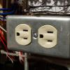
AC power outlet was placed inside the box for convenience.  It can be used for a work light and a soldering iron.
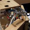
When needed, a holder for hot soldering iron can be placed on top. This is one of my better ideas.
Other Ideas
Place terminals on top of the layout, not under it.   This also includes switch machines for turnout control and their connections.  Anything that can swing out or roll out for easy access is a great idea.
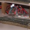
Many terminals are located on the table top near their origin.  This strip shows connections from IR detectors in the staging yard.
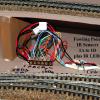
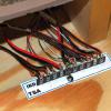
Connector strip for track section feeder wires near Prospector Flat.  I use the function and/or location in the strip label designation.  Here it is "TS" for track sections and "A" for the strip number.  The terminals on the strip are numbered.
Connector strips located near Snowshoe Pass.  Connections are for IR detectors.
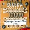
Resistor network for controlling the current of indicator LED's in a control panel.  This simplifies the clutter and the connections.
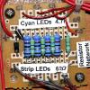
Another resistor network board with feeders to 2 different sets of LED's.  It would be simpler to use 2 boards, but space is a big concern.
Access panel in fascia for a switch machine.  This one could not be mounted on top.
To play slide show, click on the 1st picture.
Please check back for future additions to this page.